Tiếng Việt
Hydraulic Cylinder Structure, Specifications, and Operating Principles
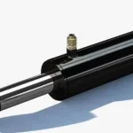
Hydraulic cylinders, also known as hydraulic rams, are one of the most critical components in a hydraulic system. They have the ability to convert hydraulic energy into mechanical energy, creating powerful pushing or pulling forces to perform heavy tasks across many industries. Let’s explore the details of hydraulic cylinder structure, technical specifications, and operating principles.
Hydraulic Cylinder Structure
Cylinder Body (Barrel)
The cylinder body is a hollow cylindrical shape, precision-machined to ensure tightness and reduce friction. This component is usually made of steel or cast iron, capable of withstanding high pressure and resisting corrosion.
The cylinder body contains the hydraulic oil, withstands the oil pressure, and guides the movement of the piston.

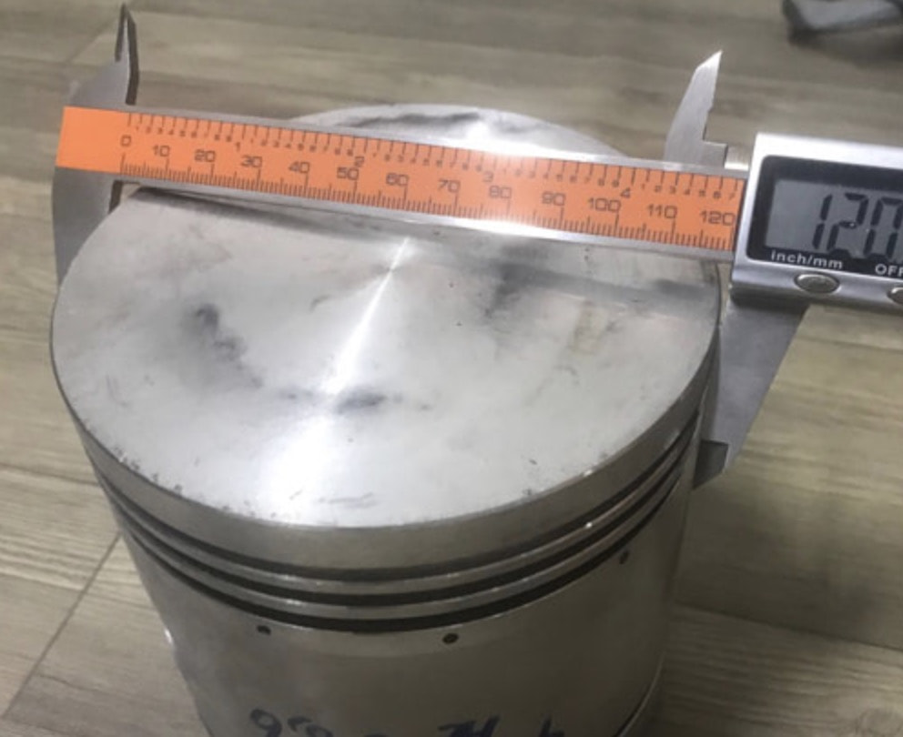
Piston
Pistons are circular discs, precision-machined to fit perfectly within the cylinder body. This part is made of steel with high hardness and durability.
The hydraulic piston functions to divide the oil chamber into two parts, receiving pressure from the hydraulic oil and moving linearly within the cylinder body.
Piston Rod
The piston rod is a solid cylindrical bar connected to the piston by bolts or nuts. It is made of alloy steel with high hardness and durability, often chrome-plated to prevent corrosion.
Function: Transmits force from the piston to the outside to perform pushing or pulling work.
Cylinder Head & Cap
The cylinder heads are covers attached to both ends of the cylinder body using bolts or threads, made of steel or cast iron for high strength.
Function: Seals both ends of the cylinder body, houses the oil inlet and outlet ports, and sometimes includes cushioning components.
Hydraulic Seals
Hydraulic seals come in various shapes such as O-rings, V-rings, U-cups, and wiper seals, made of rubber, polyurethane, PTFE, or other elastomeric materials.
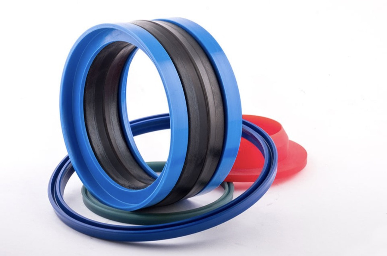
This component functions to prevent hydraulic oil leakage between moving parts, ensuring the system remains airtight.
In addition to the main parts above, the hydraulic cylinder structure also includes supplementary components depending on function and type, such as:
- Oil lines: Carrying hydraulic oil into and out of the cylinder.
- Control valves: Controlling the direction and flow rate of hydraulic oil into the cylinder.
- Cushions: Reducing the piston’s movement speed when it reaches the end of its stroke.
- Stroke sensors: Detecting the position of the piston.
Hydraulic Cylinder Specifications
General Parameters
Piston Diameter (D): The diameter of the piston inside the cylinder, measured in millimeters (mm) or inches. This is the direct factor determining the cylinder’s pushing force. The larger the piston, the stronger the force.
Piston Rod Diameter (d): The diameter of the rod, also measured in mm or inches. A larger rod can withstand higher loads but simultaneously reduces the effective area of the piston during retraction.
Piston Stroke (S): The maximum travel distance of the piston from the starting position to the end position, measured in mm or inches. The stroke determines the cylinder’s range of motion.
Working Pressure (P): The maximum pressure the cylinder can withstand during operation, usually measured in bar or MPa. Exceeding the working pressure can cause damage or cylinder failure.
Piston Cross-sectional Area (A): The area of the circle created when cutting through the piston on a plane perpendicular to its axis.
Test Pressure (Pt): A pressure higher than the working pressure, used to check the strength and tightness of the cylinder before it is put into service.
Oil Flow (Q): The volume of hydraulic oil passing through the cylinder per unit of time, usually measured in liters per minute (l/min) or m³/s. Oil flow affects the piston’s movement speed.
Theoretical Push/Pull Force (F): The maximum force the cylinder can generate under ideal conditions, calculated by the formula: F = P * A (where A is the effective area of the piston).
Actual Push/Pull Force: The actual force of the cylinder is usually smaller than the theoretical force due to friction losses and other factors.
Operating Temperature (°C): The temperature range within which the cylinder can operate safely.
See more:
Hydraulic Cylinder Reference Table
A hydraulic cylinder reference table is a useful tool to help you determine technical specifications based on piston diameter, working pressure, and stroke. You can find these tables on manufacturer websites or in specialized technical documents.
Refer to the manufacturer’s catalog or technical documentation for exact specifications for each cylinder type.
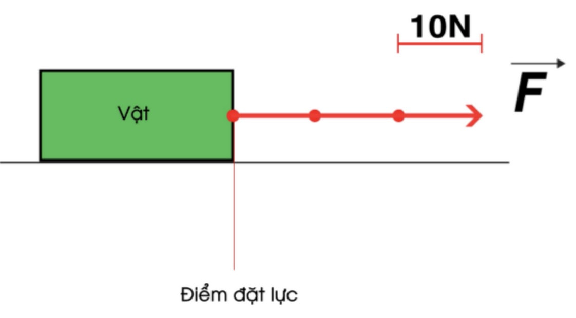
Formula for Calculating Hydraulic Cylinder Push Force
The push force of a hydraulic cylinder is calculated using the following formula:
F = P * A
Where:
* F is the cylinder push force (N)
* P is the working pressure of the cylinder, usually specified by the manufacturer (Pa)
* A is the cross-sectional area of the piston (m²)
- A = π * r²
- π (pi): A mathematical constant, approximately 3.14
- r: Piston radius (half of the piston diameter)
Example:
A hydraulic cylinder has a piston diameter (D) of 100 mm and a working pressure (P) of 10 MPa (100 bar). Calculate the push force of this cylinder.

Calculation Steps:
Step 1: Calculate the piston cross-sectional area (A):
- Piston radius (r) = D/2 = 100 mm / 2 = 50 mm = 0.05 m
- Piston cross-sectional area (A) = π * r² = 3.14 * (0.05 m)² = 0.00785 m²
Step 2: Calculate the cylinder push force (F):
- F = P * A = 10 MPa * 0.00785 m² = 78.5 kN (kilonewtons)
Result:
The push force of the hydraulic cylinder in this example is 78.5 kN.
Operating Principle of Hydraulic Cylinders
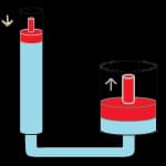
Hydraulic cylinders operate based on Pascal’s Principle: Pressure applied to a fluid in a closed container is transmitted undiminished in all directions.
When hydraulic oil is pumped into the chamber behind the piston, the increasing pressure pushes the piston forward, creating a push force.
Conversely, when hydraulic oil is pumped into the chamber in front of the piston, the piston moves backward, creating a pull force.
Video describing the operating principle of a hydraulic cylinder
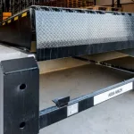
Specific Example:
Suppose a cargo truck needs to unload goods into a warehouse. A dock leveler is controlled to rise, creating a bridge between the warehouse floor and the truck bed. Once unloading is finished, the platform is lowered back to its original position.
During this process, the hydraulic cylinder plays the role of creating push force to lift the platform and pull force to lower it. The hydraulic oil pressure in the cylinder is controlled by a system of valves and a hydraulic pump, ensuring the dock leveler operates stably and safely.
Conclusion
A clear understanding of hydraulic cylinder structure, specifications, and operating principles will help you select and use them effectively, ensuring safety and increasing the lifespan of the system.
Nội dung có liên quan:
-
 What is a Loading Dock? What does a Loading Dock system include?
Is your business facing difficulties in transporting goods? Is loading and unloading taking too much time and increasing costs? Have you researched solutio...
What is a Loading Dock? What does a Loading Dock system include?
Is your business facing difficulties in transporting goods? Is loading and unloading taking too much time and increasing costs? Have you researched solutio...
-
 Differences Between Freight Elevators and Goods Hoists
Choosing between a freight elevator and a goods hoist is always a difficult puzzle for many businesses. Understanding this, Naltako will help you solve the...
Differences Between Freight Elevators and Goods Hoists
Choosing between a freight elevator and a goods hoist is always a difficult puzzle for many businesses. Understanding this, Naltako will help you solve the...
-
 Hydraulics: Concept, Structure, and Basic Operating Principles
Hydraulics is a vital technology, widely used in modern life. From industrial machinery like dock levelers to vehicles, this system plays an indispensable ...
Hydraulics: Concept, Structure, and Basic Operating Principles
Hydraulics is a vital technology, widely used in modern life. From industrial machinery like dock levelers to vehicles, this system plays an indispensable ...
-
 Dock Shelter and Dock Leveler: The Perfect Combination for Your Warehouse
Is your warehouse operating inefficiently, with high risks of cargo damage and low productivity? Don't worry, the optimal solution is here! The combination...
Dock Shelter and Dock Leveler: The Perfect Combination for Your Warehouse
Is your warehouse operating inefficiently, with high risks of cargo damage and low productivity? Don't worry, the optimal solution is here! The combination...
-
 What is a Raised Floor? What are the components of its structure?
Raised floors, hydraulic dock levelers, and access floors are popular types of flooring widely used in modern construction engineering today. To learn deta...
What is a Raised Floor? What are the components of its structure?
Raised floors, hydraulic dock levelers, and access floors are popular types of flooring widely used in modern construction engineering today. To learn deta...
-
 What is Hydraulic? Everything You Need to Know About Hydraulics
"Hydraulic" is certainly a term that many people are interested in. In Vietnamese, it translates to "thủy lực." Today, common industrial machinery within h...
What is Hydraulic? Everything You Need to Know About Hydraulics
"Hydraulic" is certainly a term that many people are interested in. In Vietnamese, it translates to "thủy lực." Today, common industrial machinery within h...
-
 What is a food lift?
Food lifts are commonly found equipment in large restaurants and hotels. They are easy-to-use vehicles due to their compact and safe design. Improving qual...
What is a food lift?
Food lifts are commonly found equipment in large restaurants and hotels. They are easy-to-use vehicles due to their compact and safe design. Improving qual...
-
 Guide to selecting used hydraulic cylinders effectively
Hydraulic cylinders play a vital role in hydraulic systems by providing high working efficiency. Currently, many people use used hydraulic cylinders to sav...
Guide to selecting used hydraulic cylinders effectively
Hydraulic cylinders play a vital role in hydraulic systems by providing high working efficiency. Currently, many people use used hydraulic cylinders to sav...